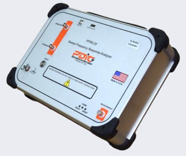
PFRS-25
Sweep Frequency Response Analyzer
• Wide dynamic Ranger > -150 dB (+10 dB to <-140dB)
• Short test time per trace < 20 Secs (20 Hz 2 MHz)
• Quick Test for connection integrity check : 6 secs
• Open Ground loop detection for reliable test data
• USB and Bluetooth communication
• Test voltage 0.2-24 V P-P
• Frequency Range 0.1 Hz—32 MHz
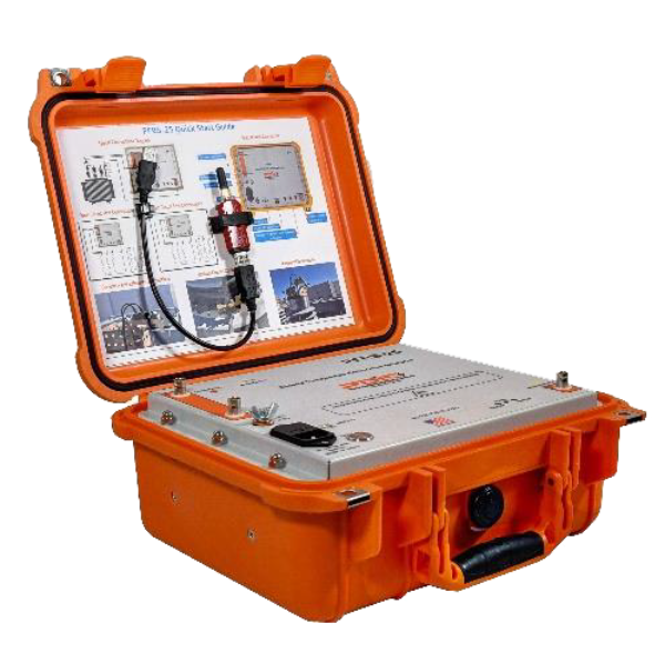
• Light weight field portable enclosure (9 Lbs.)
Introduction:
The PFRS-25 compares a transformer’s frequency response to previous results to verify its mechanical integrity. The PFRS-25 instrument is compliant with applicable international IEC and IEEE standards and guidelines (IEC 60076-18 and IEEE C57.149.2012).
Each transformer has a unique frequency response & changes in transformer mechanical geometry can modify it. Movement or transit can cause these alterations. If the transformer has excessive current due to internal or external fault , the physical shape can vary. Power transformer issues can be detected by fingerprinting the transformer’s frequency response:
- Core movements
- Shorted turns or open windings
- Winding deformations
- Winding connection problems
- Broken clamping structures
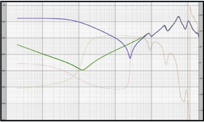
Measuring Principle:
The PFRS-25 injects the reference voltage at one end of the winding and measures voltage at the other end of the winding for a large frequency range. The ratio of measured voltage to reference voltage is plotted. The test plot can be compared to prior or reference results. Variation may indicate transformer damage. Frequency response analysis can detect turns-to-turn short circuits, transformer oil condition, core magnetization as well as winding mechanical deformation.
Applications
Transformer is a complex RLC network. Any transformer fault can change mechanical configuration. Mechanical configuration changes will alter transformer’s RLC network. The frequency response will alter due to these changes. PFRS-25 can identify the following transformer defects by comparing the trace to the reference trace or previous test traces.
- Shorted turn
- Winding movement/looseness
- Hoop buckling
- Magnetized core
- Core looseness
- Core grounding

PFRA Software
PDIC’s user-friendly PFRA software controls the PFRS-25 and analyzes test results. It can compare test results to past tests, transformer’s reference traces as well as results from a similar transformers.
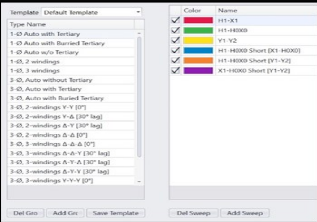
Test Plan Templates
Common transformer test plan templates are available in the PFRA. This speeds up transformer test plan creation for increased productivity. Also adding a new test plan by altering or starting from scratch is simple and easy
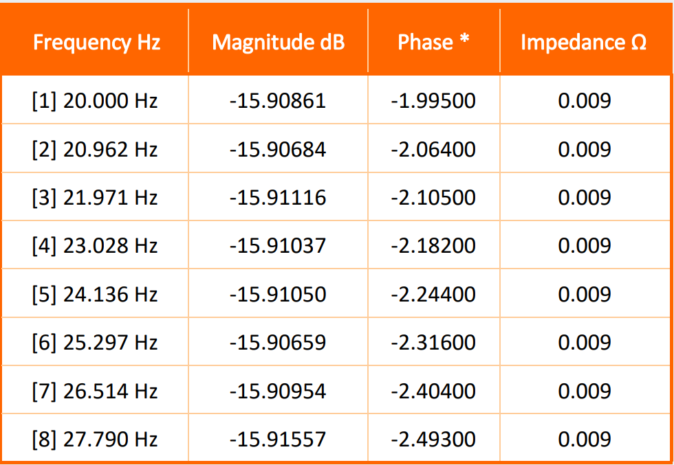
Graph and Data Views
The PFRA software can display the results in Amplitude, phase angle, impedance and test data with respect to frequency.
Test Voltage
The test voltage issettable from 0.2-24 Vp-p allows user to set the test voltage to the value used for previous tests if it is different than the typical 20 V p-p.
Customized Number of Test Points
The number of test points between a defined frequency band can be customized. The maximum number of test points for a defined trace can be set up to 42,000.
Customized Trace Data Acquisition
The trace can be configured to start from high frequency to low frequency or low frequency to high frequency to match the process followed for the previous trace.
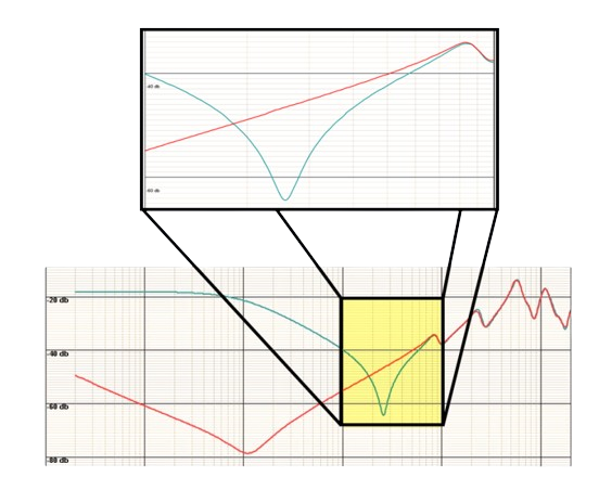
Trace Zoom Feature
For simple analysis, drag a square with the computer pointing device around any region of the trace to zoom in. When the pointing device is on the trace, the software displays the frequency (x axis) and dB value (y axis) to enable users compare traces.
Test Data Import Feature
The PFRA software can import test results of all other man- ufacturers of SFRA instruments. It can also import test results in IEC, CIGRE or CSV format.
Trace Customization
The PFRA software does not limit the number of traces that can be displayed. All or individual traces can be shown or hidden and each trace’s color can be configured for easy analysis. The trace display line thickness can be customize for better visibility and easy analysis.
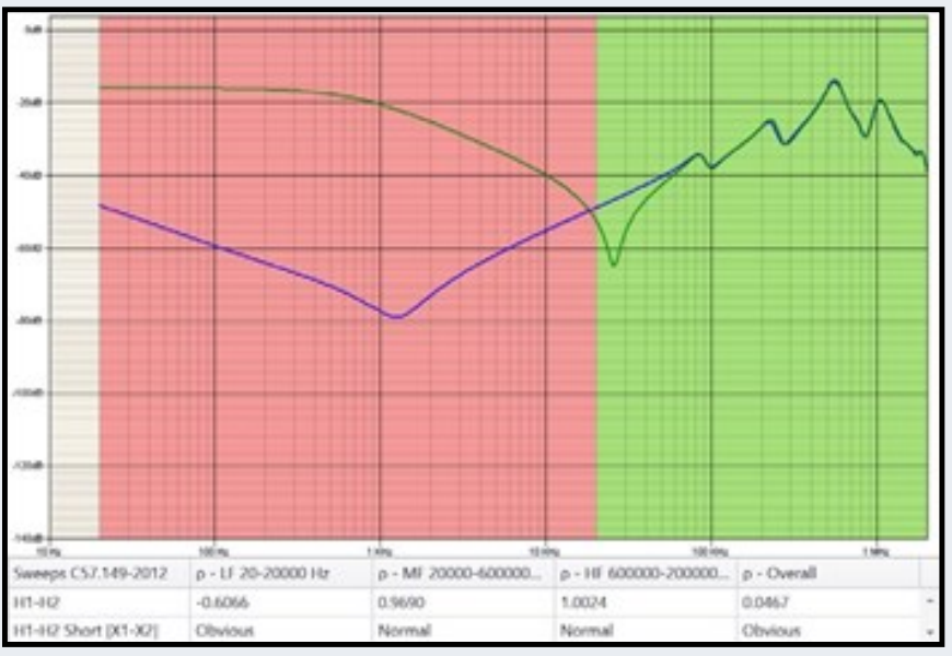
IEEE and DL/T standard Visual Indications
Comparison of traces with visual indication of Normal, suspect, severe and Obvious condition can be done per IEEE C57.149 and DL/T911 standard.
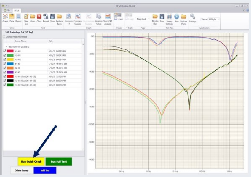
Quick Test Function
The PFRA’s quick test feature can scan the trace in under 6 seconds to confirm that the connections to the instrument are good. Any wrong, loose, or bad ground connections can be detected quickly if the quick test scan does not show the expected trace shape or shows a noisy trace.
Test Data Import Feature
The PFRA software can import test results of all other manufacturers of SFRA instruments. It can also import test results in IEC, CIGRE or CSV format.
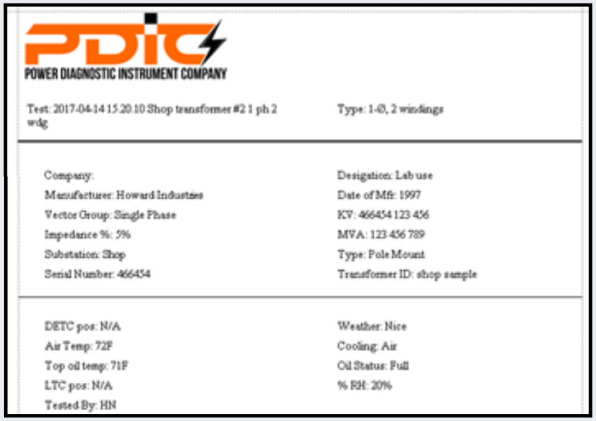
Test Report Customization
Test reports can be customized with a custom header and logo.
Fastest Sweep Time
The lightweight, field-portable PFRS-25 single box instrument diagnoses transformer mechanical integrity. It provides precise measurement accuracy of ±0.1 dB for all ratios between +10 dB and -60 dB, and ±0.3 dB for ratios above -60 dB. The PFRS-25 has the fastest sweep time of all contemporary SFRA instruments at under 20 seconds (20 Hz–2 MHz), minimizing transformer testing time.
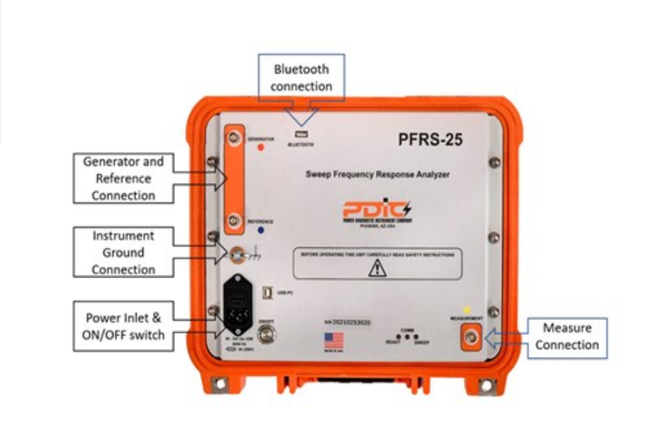
Computer Interfaces
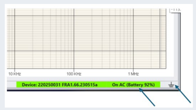
Bluetooth enables users to be away from the instrument and transformer under test. This feature is useful in bad weather. User can be away from instrument while the PFRS-25 instrument can be placed on the transformer. The unit displays a connection status on the front panel and in the software. Standard USB 2.0 is also included.
Optional Battery Backup
Built-in battery backup is useful option when AC power is unavailable. Users can test for 4 hours without recharging the 12 V, 3.2 AH battery. While the battery charges, the instrument can be used with AC power. When connected to the instrument, the software displays battery charge level.
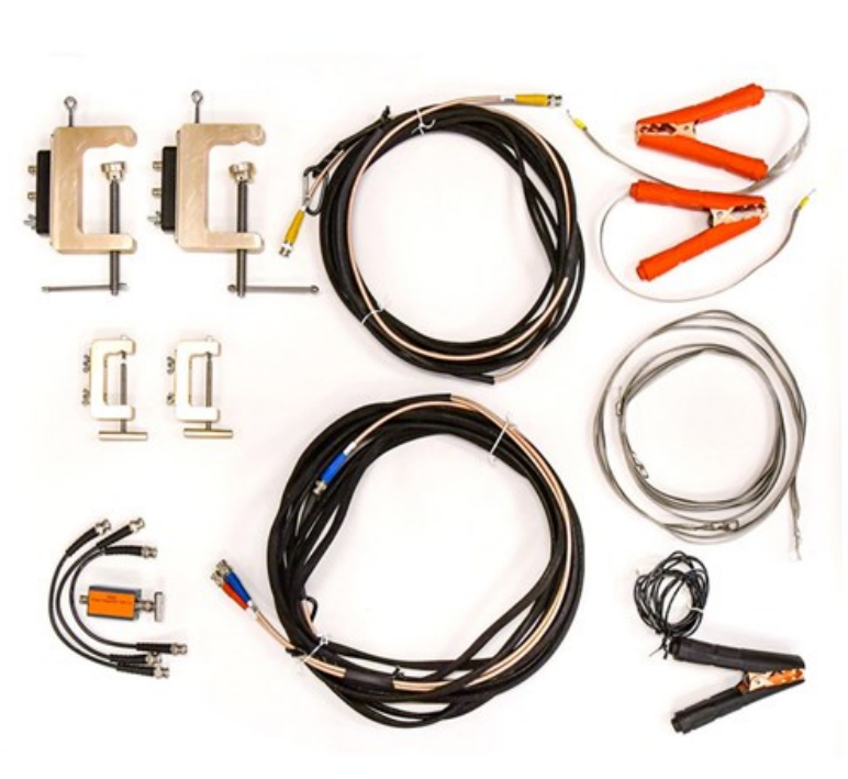
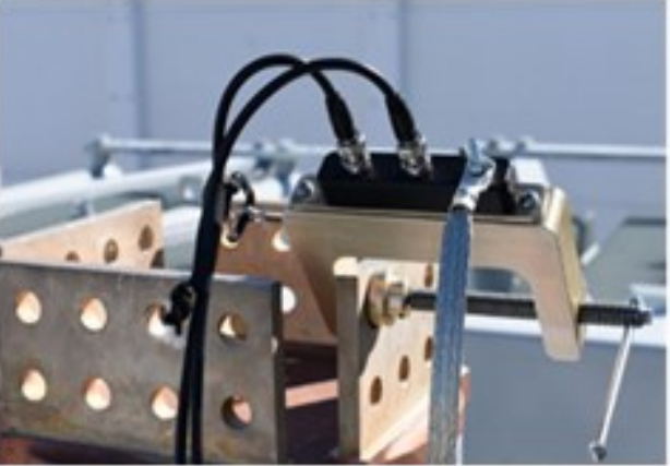
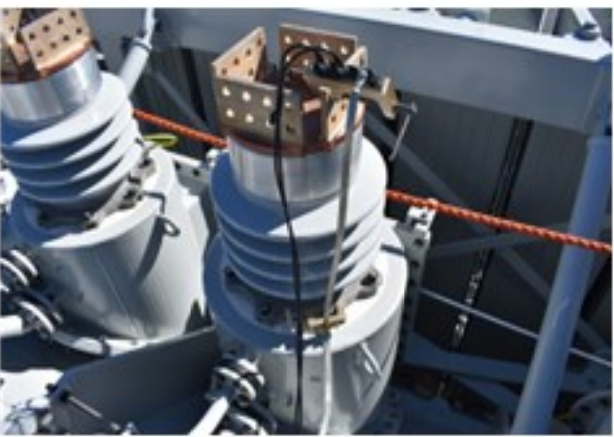
Clamps and Test Cables
All bushing connections can use simple universal C clamps with BNC connectors. They easily accept flat and round bushing terminations. Similar ground clamps make ground braid hookup easy. Alternatively, the test kit also comes with an option of integrated test leads with alligator clips upon request.
Documentation
Each instrument comes with a manual. The instrument lid has a quick start guide sticker. A quick start guide gives short circuit and open circuit test connection information and shows how to create proper connections.
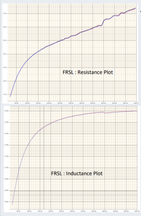
Frequency Response Stray Loss (FRSL)
FRSL (Frequency Response Stray Loss) is a cutting-edge electrical test method incorporated into PFRS-25 software, meticulously designed to swiftly identify intra-strand short-circuits and overheating within transformer windings. With FRSL, AC resistance is precisely measured across discrete frequencies ranging from 15 to 400 Hz, allowing for pinpoint accuracy in detection. Through intuitive visual analysis, deviations indicative of strand-to-strand short-circuits are promptly identified, empowering proactive maintenance initiatives. Recommended for commissioning or acceptance tests, FRSL provides vital insights into transformer health. More over, results are validated through cross-checking with Dissolved Gas Analysis (DGA), ensuring a comprehensive assessment and facilitating the implementation of optimized performance management strategies
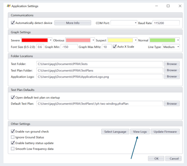
PFRS-25 : Instrument Diagnostic
Our innovative instrument features built-in diagnostics, facilitates the users to monitor the test and the performance of PFRS. The advanced software that comes with PFRS-25 monitors the data quality for all parameters, enabling the users to meticulously analyze data from each measurement channels, ensuring the optimal quality of acquired data. Additionally, the software continuously monitors the performance of battery charge level and conveniently displays the status of battery charge on the home screen. The battery level indicator employs a color-coded system (green, yellow, or red) based on charge level, providing intuitive feedback for seamless operation.
The software employs advanced tools to continuously monitor the PFRS-25 hardware to assist the users in diagnosing events of inadequate performance. The latest design of PFRS-25 ensures that the quality of ground is always monitored not only prior to the test but also during the test. Moreover, the software logs all activities and messages exchanged between the instrument and software, aiding users in diagnosing any issues if the instrument does not perform as expected in the field. The overall design of the PFRS-25 can diligently monitor the ground integrity and displays status of ground integrity on home screen ensuring performance of SFRA test with high standards of quality.
PFRS-25 : Alternate Enclosure
PFRS-25 is also available in alternate packaging. It provides same functionality as our standard packaging in field portable ABS plastic case. It provides alternative packaging to suit user preference.
Technical Specifications : PFRS-25
General | |
|---|---|
AC Power Supply | 90 – 264 V AC, 47 – 63 Hz |
Internal Battery | 4.8 Ah, 58Watts (up to 4 hours of operation) or custom size |
Measurement Principle | IEC 60076-18 and IEEE C57.149.2012 |
Dimensions | Std Enclosure 13″ x 11″ x 6″ (34 cm x 29 cm x 15 cm) Alt. Enclosure 14″ x10″ x 3.9″ (35cm x 25 cm x 10 cm) |
Weight | 9 lbs. (4.0 Kgs) in the field rugged ABS Enclosure , 7.5 lbs (3.4 kgs) in alt packaging |
Carry Case | 31.0 lbs (14 Kgs) 20” x 15” x 10” (50 cm x 37 cm x 25 cm) |
Standards | |
EMC |
EN 61326-1:2013 EN 55011 Class A Group 1 EN 61000-4- 2,3,4,5,6,8,11,2004/108/EC |
LVD | 2006/95/EC |
Safety | IEC 61010-1 EN 61010-1 UL 61010-1 |
Measurement
| |
Frequency Range | 0.1 Hz – 32 MHz, user selectable |
Frequency Resolution | 0.01% OR 0.001Hz |
Frequency Accuracy | 0.01% (measurement error) |
Level Resolution | 0.0005 dB
|
Samples per Trace | Up to 42,000 points, user selectable, recommended 1,050 points |
Measurement Time | < 20 S, fast setting 6 S (20 Hz – 2 MHz) |
Points Spacing | Log, linear, or both |
Sweep Settings | 10 Hz to 2 MHz (Typical and user selectable) |
Internal Noise Level (average) | > 140 dB |
Dynamic Range | > 150 dB |
Accuracy | ±0.1 dB from +10 to -60 dB and ±0.3 dB below -60 dB |
Communication | |
PC Communication | USB and Blue Tooth. Includes PC software |
Analog Input
| |
Channels | 1 |
Compliance Voltage | 0.2 – 24 V p-p |
Measurement voltage at 50 Ω | 0.1 – 12 V p-p |
Channel Protection | Short-circuit and over voltage protection |
Sweep Direction | Low to high or high to low (user selectable) |
Frequency Range | 0.1 Hz – 32 MHz, user selectable |
Analog Output | |
Channels | 2 |
Sampling | Simultaneous |
Frequency Range | 0.1 Hz – 32 MHz, user selectable |
Input Impedance | 50 Ω |
Sampling Rate | 100 MS/s |
Environment | |
Ambient Temperature | Operating: -26°C to +55°C (-14°F to +131°F) |
Storage: -26°C to +70°C (-14°F to +158°F) | |
Humidity | < 95% RH, non-condensing |